BEAMLINES >

BL25 - MINERVA

OPTICS CHARACTERIZATION

IM-Banner-MINERVA-Left

IM_Banner_MINERVA_376-276

You are here: Home / Beamlines / BL25 - MINERVA

DESCRIPTION

MINERVA is a soft X-ray beamline designed to support the development of the NewATHENA mission (Advanced Telescope for High Energy Astrophysics) and is funded by the European Space Agency (ESA) and the Spanish Ministry of Science and Innovation. The beamline design is entirely based on the monochromatic pencil beam XPBF 2.0 (Physikalisch-Technische Bundesanstalt, PTB BESSY II) and provides metrology capabilities to integrate stacks produced by cosine company into a mirror module (MM) and characterize them. Interoperability between MINERVA and XPBF 2.0 will be preserved to reinforce and boost the production and characterization of the mirror modules.

MINERVA takes port 25 at the ALBA experimental hall, which provides optimal distribution of the components in the experimental hall, and allows for future upgrades (like adjustment for possible reduction/extension of the MMs focal length). This port is fed by a bending magnet source, and is relatively near the vacuum laboratory clean room.

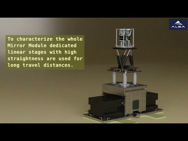
The beamline operates under Ultra High Vacuum conditions (UHV) from the source to the exit of the photon shutter, where a vacuum window will separate them from the rest of the beamline. Downstream the vacuum window, the beamline will operate under High Vacuum conditions (HV) (10-5 mbar). The beamline provides stable temperature and clean environment around the sample station, and is equipped with angle-measuring devices (autocollimators) and an in-vacuum  hexapod to control the MMs orientation during measurements. To ensure the accuracy of the geometrical configuration required by the data analysis, the beamline assesses the absolute distance between the fluorescence screen and the MM origin. This measurement relies mainly on the performances of laser tracking technology and the high positioning repeatability of the mechanics. For instance, optical targets (cube reflectors) are firmly fixed to the detector for a continuous read out of its position. The main hexapod inside the vacuum chamber also benefits from laser tracker technology for accurate positioning calibration. In the situation where a single laser tracker is not enough to achieve the required knowledge between the MM and the detector, a second laser tracker might be used close to the sample chamber. All hardware components are integrated to the standard ALBA control system, which provides also continuous monitoring of the Equipment Protection System (EPS) and Personnel Safety System (PSS). The control system includes macro execution and flexible scripting to allow for scan automation. Data acquisition allows recording the detector images together with the necessary configuration parameters of the beamline.


STATUS

MINERVA is in operation, it successfully passed the acceptance review meeting and was endorsed by the ESA at the end of October 2023.

IM-MINERVA-1  IM-MINERVA-2


PERFORMANCE

MINERVA provides photons with a fixed energy of 1.0 keV with a residual divergence below 1 × 1 arcsec2 rms. The beam dimensions at the mirror module is adjustable from 10 × 10 μm2 up to 8 × 8 mm2.


OPTICS - BEAMLINE LAYOUTS 

MINERVA follows the optical layout of XPBF 2.0 and is sketched in Figure 2. It shows the three main components of the beamline: the multilayer monochromator enclosed in the optics hutch, the sample chamber inside a temperature-controlled enclosure, and the detector tower.  One can find the distribution of the following optical elements:


  • The source is one bending magnet of the ALBA storage ring.
  • A filter unit consisting of one Si3N4 membrane coated with a thin Al deposition. This filter removes the visible light reflected by the M1 mirror.
  • The front-end elements. The last component of the front-end is the trigger unit, which is placed at the first element of the optics hutch.
  • A toroidal mirror (M1) with a multilayer coating. The mirror deflects the beam inboard, with a total deflection angle of 14 degrees (nominal incidence angle of 7 degrees from mirror surface). It collimates the beam in both the horizontal and vertical planes. Its reflective surface has a multilayer coating that selects a narrow bandwidth of the incoming radiation at the nominal energy of 1.0 keV.
  • A set of pinholes, of several sizes, ranging from 10 µm to 500 µm in diameter. These apertures allow reducing the size of the beam that reaches the sample to a smaller well-defined diameter. The pinholes are installed on a motor actuated linear feedthrough, in a 4 way cross vacuum chamber.
  • A photon beam shutter which includes a fluorescent screen beam diagnostic unit that allows visualizing the beam right upstream sample station.
  • A valve equipped with Si3N4 window, which separates the upstream UHV section from the downstream HV.
  • A four-blade slit system. The four blades are motorized and encoded, and allow for apertures from fully closed to more than 10 mm in aperture, both horizontally and vertically.
  • The sample station, which includes an in-vacuum hexapod and 2 linear stages for vertical and horizontal translations.  The mechanical arrangement allows positioning the mirror modules (MM) under test at the right position and orientation with respect to the incoming beam.
  • A flight-tube, which links the sample station to the detector. The flight-tube preserves the vacuum along the 12 meters long beam path between the MM and the detection system. It can adapt its position to the range of the different deflection angles (its orientation from the floor can range from horizontal to about 7 degrees upwards). In addition, its adjustable length can compensate motion of the detection system position.

The imaging detector consists of a fluorescent screen coated at a viewport at the downstream flange of the flight-tube and imaged by a visible light 2-dimensional visible camera. To allow for the different deflection of the mirror modules, the detector is mounted on a support tower that allows changing its height from 1.4 m from the floor to about 2.7 m. Also for calibration purposes, the direct beam (not deflected by any MM) can be accessed.

Optical layout of MINERVA

Figure 2. Optical Layout of MINERVA


EXTERNAL LINKS

https://www.cosine.nl/

https://www.cosmos.esa.int/web/athena