ALBA Synchrotron
In the figure below, a schematic layout of the optical components of the BOREAS beamline is shown, both from above and side view. A detailed description of the functionality of the various optical elements is given in the Conceptual Design Report of the XMCD beamline.


In brief, the beamline consists of three sections:
- the first section is composed of the plane and toroidal mirrors (PM and TM, respectively). Their function is to absorb most of the heat load delivered from the source and to prepare the beam for the monochromator by focusing it in the vertical plane (which is the dispersive plane of the monochromator) at the entrance slit (and, in the horizontal plane, 2 m upstream at the exit slit);
- the second section consists of the monochromator: this is based on variable line spacing (VLS) plane gratings (PGs), working at a fixed included angle (175° in combination with the spherical mirror SM1 or 177° in combination with the spherical mirror SM2). The monochromator is equipped with both entrance and exit slits and is dispersing in the vertical plane;
- the third section comprises the refocusing optics, consisting of two bendable mirrors arranged in a Kirkpatrick-Baez geometry, where the first mirror (PE1) is vertically focusing, while the second mirror (PE2) is horizontally focusing. This system allows you to focus the beam at either of the two experimental stations.
Grating mirror combinations
80 – 300 (800) eV | SM1+LEG |
250 – 600 (1400) eV | SM2+LEG |
380 – 1700 eV | SM1+MEG |
950 – 3000 eV | SM2+MEG |
600 – 2100 eV | SM1+HEG |
1900 – 4500 eV | SM2+HEG |
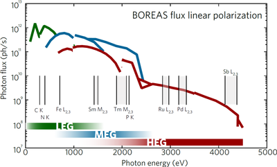
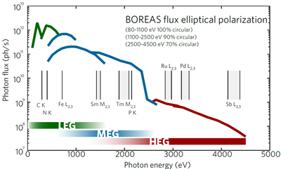
Shown below are some plots of the typical beamline photon flux using the different gratings and mirror combinations available at the beamline, and for the various polarizations of the EPU. Flux values are estimated from intensity measurements made using an AUXV100G diode downstream at the location of the last beamline optical component.
In the measurements, the accumulated storage ring current was around 100 mA, and nominal slit settings were used, i.e. 15 micron opening for the vertical entrance (VES) and exit slits (VXS). Resolving power is about 7,500-10,000 with VES/VXS=15/15 micron slits. Higher resolving power, approx 15,000 or greater, can be attained for more extreme exit slit settings, such as 15/5 micron slit settings, whereas intensities are almost linear on the vertical exit slit opening (vertical beam FWHM at the entrance slit is estimated to be typically within 5.5-7.5 micron range). A number of combinations, including choices between Gold or Nickel or Silicon (uncoated) stripes on the first plane mirror, slits, etc...can result in slightly different numbers, but these values are representative.